I’m not at Superbooth, but one of our OSCars is. There have been a few sleepless nights to get it over the line. Paul Whittington’s more camera-ready than I am. Here he is, surrounded by synths I’ve had a hand in designing.
(Three models is just enough to use the verb ‘surrounded’, I think. Really, they’re all co-production credits. I’ve laid out a lot of boards, written a lot of firmware, and dealt with a lot of manufacturing stuff. But I don’t know how one crosses the floor in this industry from craftsman to auteur.)
In the smoke-and-mirrors department, there’s still a lot OSCar doesn’t do. The list begins with saving patches, arpeggiating, sequencing, syncing, and the PWM and waveform-designing features, all of which are going to benefit from some user interface reappraisal.
I also need an antialiasing day to prove to myself that I have determined the source of it all, and that I can fix it. In theory, OSCar will never alias: as covered in previous posts and talks ad nauseam, its sample rate is locked to the note frequency, so aliases become harmonics.
Most of what you hear on that video, especially obvious on the Init Patch (nowhere to hide with a full-range sawtooth), is aliasing from a different source. The Superbooth unit has an uncorrected design fault on the CV filters, which I didn’t spot in time. The voltage references to the DAC therefore have a lot of the 35kHz CV carrier frequency on them, so the DAC dutifully turns into an amplitude modulator, makes a bunch of arbitrary sidebands, and then sample-and-holds the result. That’s what you’re hearing. When the filters work as intended, those sidebands will be more than 90dB down. I live in dread of finding out that the filters can still pick them out.
I think I might also have a problem with the two oscillators interacting, but that’s just a hunch: if it’s happening it’ll be caused by the accurately clocked sample-and-hold at the end of the audio chain, that’s copied from OSCar, being driven by the wrong duty cycle or having the wrong capacitance. This is why I need a day just to make sure I’ve tackled all the fidelity issues before knocking out another PCB.
Sound-wise, the other known problem to resolve is treating the PLLs that multiply up the clock. My design needs to restrict the multiplied-up clock range, which drives the sample rate, to a little over an octave, and fold over at that limit. PLLs don’t, of course, handle the step change too elegantly and you get a few clicks of complaint when that happens.
OSCar didn’t have to fold over as much. First, because it was confined to a five-octave range that a VCO can easily manage. I don’t know if customers would be happy with that now: I wouldn’t. Second, because a lot of the clock folding was done by external counters, which can change rate instantly. Chris was therefore able to run his VCOs at more than 500kHz; mine trigger an interrupt each time so I can’t go quite that quickly. All of which leaves me a little exposed. Still, nothing that a bit of solder and a lot of thought can’t fix.
The work is paying off because, apart from those flaws, it sounds pretty good (judge for yourself: playing starts at 4:20). This is pretty much the most success I’ve had from any design’s version-one hardware, although it’s kind of version two because I built that Z80 clone and learned from my mistakes.
The downside of presenting a first-issue board is that it’s actually a sign that the second issue is overdue. The one at Superbooth is about four iterations deep of learn-something-fix-something. At some point you need to clean the slate, but I want to run a couple more tests first.
Everyone’s a critic
We’re long past the stage where it’s too early to solicit criticism. There’s always the risk of misaligned expectations, though. One of the certainties of a creative profession is that the first tentative outing will be judged by the same standards as a final product. One needs to learn to accommodate this kind of thing:
It’s peculiarly gratifying to be reminded about why I’m already anxious. But, first, luxury product: price reflects performance, effort, and the fact that exclusivity is expensive. One selfish reason for keeping this blog is that the act of writing helps to clarify and focus the mind. But another is to signify the amount of thought, care, and skill involved in completing a synth, even — or especially — if the template is a product that already exists.
Lest we forget, even if you scraped the new-old-stock parts together, got the PCBs faithfully copied, and tooled up to reproduce a design to Anthony Harrison-Griffin’s original spec, you could not legally sell a part-for-part replica of an OSCar today because it wouldn’t pass an EMC test and earn its FCC or CE accreditation. From time to time, of course, individuals do produce a short run of clones after this fashion, but they’re doing it out of love, are too small to go after, and frankly, you’d have to be a special kind of dickhead to want to spoil their fun.
So first, we need to get to a completely working OSCar with production parts and a compliant design. Which we’ve also been fixing, hardware- and software-wise, in myriad ways, so it’s less fragile and electrically quieter than the original. We then add a load of conveniences: USB bus power, velocity sensitivity, comprehensive MIDI control, a frequency range that takes it down to floor-shaking frequencies, and numerous other features that people either want or expect from a modern instrument. Even if you think minimum wage is ten times too much to pay to watch me having fun doing a thousand hours of unforgiving maths, this is a bargain.
Second, we have Chris’s OSCar #1 so, when we decide to declare it ready, we’ll do so with authority and evidence. Frankly, what matters to me? Not being the person who dares to presume without merit on Chris Huggett’s legacy, and mucks this up.
There’s a danger that design work slows down because I waste too much time enjoying my own prototype. Not yet, though: my excuse this week will be that I’ll need to go and think about something else for a while until my eyes uncross again. Perhaps I’ll disassemble the arpeggiator.
It looks like ADC is about to get around to releasing my talk from last year. That talk video is an hour-long digest of the most interesting parts of this story, about five months behind where I am now.
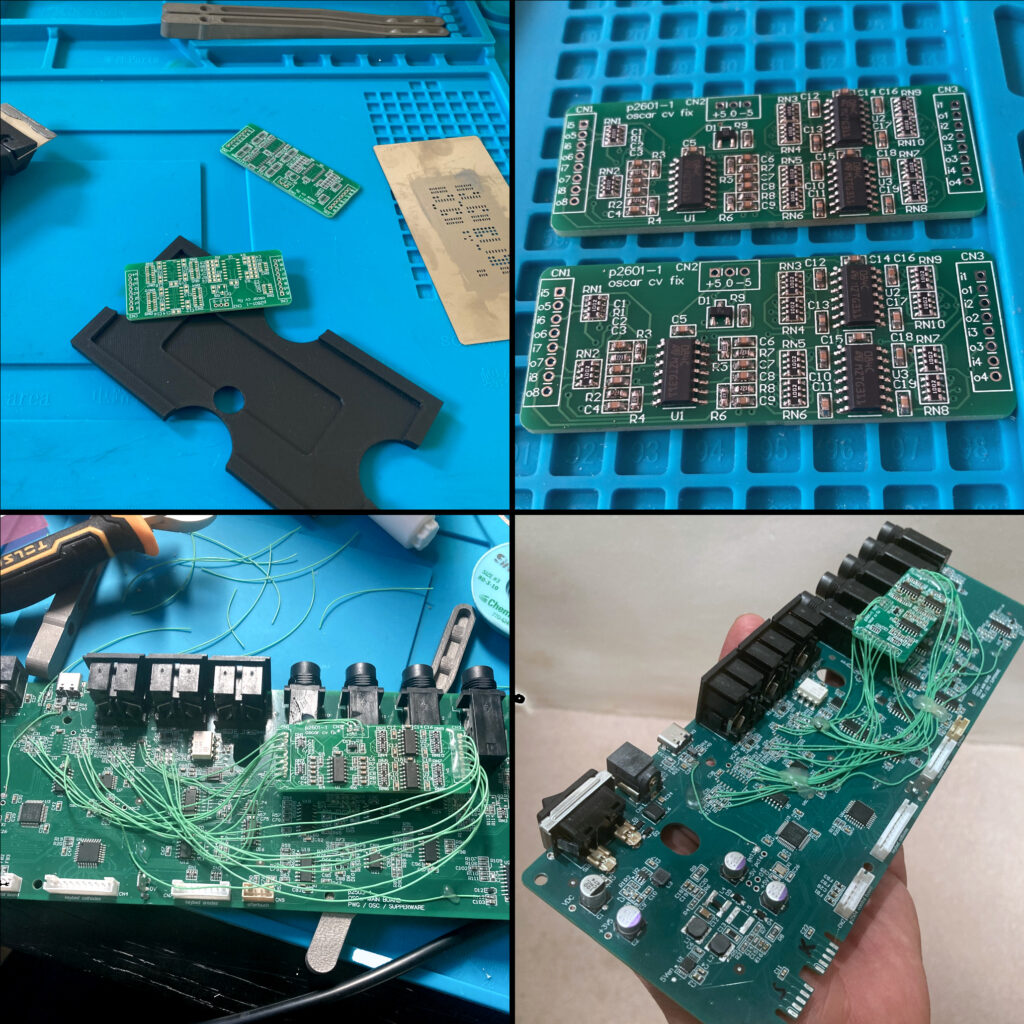
Yesterday, I handed over a prototype to send to Superbooth. The firmware is crap at the moment, but I’ve got a week to improve it. I ended up installing this monstrosity:
This is exactly the scale of bodge that I’d usually advise against: a two-hour mission of surgery that is barely worth doing over scrapping the board.
There is a miracle to this that I still cannot take for granted. I spent hours in the late 90s labouring over Veroboard prototypes, debugging track cuts and misplaced wire runs and solder shorts. As recently as 2010, a 2-layer plated-through PCB like this would have taken a minimum of three weeks to manufacture and cost about £400, and I’d have had to pay. These PCBs arrived from JLCPCB in Hong Kong five days after I placed the order, and cost me about £25 including shipping. The low cost and short turnaround of custom PCBs has completely changed our profession.
(All that said, I’m experimenting with the head tracker at the moment. Being a flex-rigid board makes these a special order even in Asia. It was a throwback to the Old Ways: ten bare PCBs did indeed take more than a month to arrive and cost over £500.)
Back to our story. A few postings ago, I remarked that I missed out some level-shifting circuitry to give the control voltages their proper range. Flippantly, I said:
Just don’t ask me to wire one into a rev. 1 prototype, unless you’re sponsoring me for charity.
My attitude towards tempting fate is to do it as often and as brazenly as possible, to the extent that people begin to edge away. Wherever manufacturing is concerned, one should tease all possible misfortune out of the gods at the earliest opportunity, as it only gets more expensive later on. I really ought to know better because, of course, it turned out to be a lot worse than I’d thought. OSCar doesn’t produce a 0–5V range of control voltage, but about −3.5–+3.5V. I overlooked this for a few reasons, but two are most important.
First, I lent out my half-speed OSCar clone, which meant I didn’t have a reference circuit to hand. The clone stopped working properly at some point during ADC, and I couldn’t be bothered to fix it. The DAC still outputs control voltages on schedule, but something weird goes on when I try to play a note, like it’s resetting. Nobody alive is better positioned to debug it than me, but frankly I didn’t have a good enough reason to get it going again and I’m spread thinly enough.
Second, the DAC0808, that heroic high-speed 8-bit mono DAC that OSCar uses for everything, has a data sheet that is particularly short on description. It has none of the courtesies that manufacturers provide today: no reference design with commentary; no graphs of it in use; no ready-baked formulae to relate output to input. One must analyse the equivalent circuit or, more likely, wire-wrap one into a prototype. One would then, as we used to say, ‘adjust-on-design’ around it until it served its purpose, give tolerances a cursory thought, and bake whatever arbitrary values worked into the production schematic. Long story short: its output range is bipolar but you’d easily miss it, and the 80s were a different age.
Actually, the DAC works upside-down: it sinks more current from a reference as the number you feed it increases. This current is then converted into a voltage by a separate LF351 op amp that is essentially the output stage of the DAC and inverts the signal. Such things are easy to overlook in these days of large-scale integration. It’s been more than thirty years since you would see a new DAC without the output op-amp forming an inseparable part of the same chip. (That said, the DAC0808 is still in production, complete with entirely different pinouts for the surface-mount and through-hole chip versions: something else I’ve never seen on a production chip, and a landmine that I did side-step.)
I’m not using DAC0808 in the new design. Apart from the fact it needs a parallel input — a waste of 8 general-purpose pins these days — OSCar’s ‘it’s all one DAC’ trick is not one I’ll be repeating. As I covered in my previous post, it’s ingenious, but the exquisite timing and hackery required to dispatch all the voltages to their proper amplifiers is the principal reason for OSCar’s notoriously poor reliability. If we’re being fair, the final result is also a bit ‘steppy’: the filter and separation knobs feel very granular. The separation control is actually masked in OSCar’s maths so that only the five upper bits do anything, giving it a range of 0–31. One of my rules, succinctly put, is that workarounds with crap side-effects get fixed, and this is in that category.
The new OSCar instead gets a dual 8-bit DAC, one channel for each oscillator, which sweeps much of the old glue logic away. The control voltages, meanwhile, come out of 8 channels of 11-bit pulse-width modulation, which the microcontroller gives us for free.
(Why 11 bits? Many reasons. The original OTA chip which forms the voltage-controlled filters and amplifiers, the LM13600, is no longer in production. The LM13700, which is, is similar enough given our constraints that we can use it instead. Indeed, if you’ve got sharp eyes, you’ll see that Dave Spiers’s OSCar uses one as a replacement for one of his LM13600 chips, shown briefly in this video. Its internal circuitry, though, is slightly different, such that I anticipate needing to curve the control voltage to make it sound the same. The fact that those extra three bits might reduce the granularity of the controls is a bonus. 11 bits also gets us a nice carrier frequency: 72MHz/2^11 = 35kHz. Out-of-band for one, so you won’t ever hear it, but it’s also easy to design a control-rate filter that removes it well enough that we won’t hear modulation artifacts either.)
The PWM outputs are expanded to the correct range (on my second attempt) and smoothed down to the control rate so there’s effectively no ripple at audio frequency. Hence all the hand-wiring: every control voltage needs its own PWM-to-voltage converter. That is four bipolar signals for the VCF/VCA circuits (needing two op-amps). Four monopolar signals (needing only one op-amp) are abused as volume controls. Although, as we’ve covered before, only 7 of these control voltages really get used.
It doesn’t matter at all about the oscillator signals having the wrong voltage range, as there’s an AC capacitor between the audio output and the filter input on OSCar. As long as it wiggles at the right amplitude, which it does (with care), its absolute voltage is of no concern.
I’d give you a sound demo, and I’ve been promising these for weeks, but I’m miles away from my audio interface and you’ll get one soon enough.
The 0–3.3V restriction in the prototype control voltages prevented the filters from working in their most interesting range: the high-Q and the low-frequency regimes. The side-by-side comparison made this glaringly obvious. The OSCar whistles, growls, and makes Speak & Spell noises on demand and mine, er, didn’t. Filters being the most important part of OSCar, that obviously needed fixing for a trade show.
Nineteen pieces of hand-wiring later, and a lot of glue (as it’s destined for international travel) and we have our bodge. As this was a borderline decision, I chose not to remake the whole board for a couple of reasons: most importantly, I’d have to re-equip for production and that means trusting that every component I need will be in stock, and that neither I nor the stockists will make a mistake. Second, the fear in the back of my mind was that I’d bugger it up somehow and have nothing to show.
Hand-wiring, then, away from the comfortable, well-equipped lab at home (as I’m dog-sitting), is what I ended up doing.
Fortunately the planning paid off, because the bodge worked first time. There’ll be tweaks to the range for production, as there will be for every part of this synth, and I must very soon go and make the same mess of my own R&D prototype, but this will do for Superbooth. The real test will be whether it works the second time, when me and my soldering iron are replaced by journalists and their video cameras.
Next Tuesday I’m spending an afternoon with Chris Huggett’s OSCar at PWM HQ, to find out how far I am from this prototype sounding and behaving like the original, so I can close that gap. I expect it to go about as well as any first technical rehearsal: the stated objective is to learn, but the real purpose is to instil fear.
A few features are still missing. As long as the LFOs, envelopes, filters, pitch, and VCAs are somewhat wired in, refinements can wait. Without my own fully-kosher OSCar to play, it’s surprisingly tiresome to work through two entire signal chains and prove something even as trivial as the fact that I’m sounding at the correct octave. If there’s any compensation to working blind, it’s obtaining a depth of understanding that probably surpasses Chris Huggett’s of the time. It’s anybody’s guess why I’d want or need that, though …
Anyway, Superbooth is looming. I never get to go myself, because I’m too busy sending products and features. I’ve promised some kind of playable demo, but it’s taken a lot longer than expected to make the modulation work. Such things always take time, incurring familiar long cycles of break-it-then-fix-it. But this work is also a grind: low-dopamine; high-effort; lots of carefully checking number ranges across two implementations. It breaks in funny ways in unexpected places. The code is a bit smelly, and reorganising it into something maintainable takes a lot of thought. But it’s essential, or why do this at all? Occasionally I lose half a day just moving blocks of it around, and confirming that it’s correct. All of which is making it hard to sleep, and one cannot do this kind of work during insomnia.
Knowing what to change and when is a constant problem, because old code involves a quantity of enquiry, and I find myself adding the comment ;BUG rather often: if it is broke, there has to be a reason not to fix it.
Sorry, where was I? Alex Ball makes some great videos featuring an original OSCar. And the comment thread below reveals that a couple of people at least do want to know how OSCar generates its sound. What follows is therefore a more-than-usually technical post about some of that.
Did I mention oscillators?
The short answer: OSCar’s got two wavetable oscillators. Each one scans its own table of 256 samples per period.
The long answer is that this was far harder to do in 1983 than you might expect. We end up with a circuit and implementation which is, to pull the apposite quote from @RegebroRepairs above:
SUPER weird.
Just one DAC
Remarkably, every analogue voltage that the OSCar generates — two oscillators and 7 control voltages — come out of the same mono 8-bit DAC. It gets switched a lot.
This is a slide from my still-unpublished ADC talk (and the AES talk before that: too expensive to use only once) which demonstrates what the DAC is outputting over time. I was measuring my own OSCar clone, which runs at half-speed so I can emulate the ROM and RAM using a cheap ARM chip. (That made debugging a lot easier and saved me needing to buy an EPROM programmer — more bloody stuff — but I couldn’t quite make it run reliably at 4MHz.)
The upper graph shows two sawtooth waves, of different frequencies, that the DAC is chopping between constantly: oscillators 1 and 2. The parts I’ve coloured red are where the interrupt service routine chucks out nine control voltages that OSCar also isolates and holds in separate op-amps:
All the control voltages. I did redraw this in CAD, but I’m a fan of Chris’s penmanship.
The control voltages are updated via the DAC at the beginning and end of the interrupt. I think this doubling was to let Chris measure how long OSCar spent in that routine. The trace above shows it taking about 3.6 milliseconds (call it 1.8ms at full speed), in which it updates the LFO, glide, gating, PWM, filter and pitch control voltages, and checks the voice allocator. Considering that a single multiply lasts about 80 microseconds, you can imagine the terseness of this code. The 244Hz control rate is a little low by modern standards: Mantis operates around 600Hz.
Why nine control voltages? OSCar uses 7 for internal amplifiers and filters; there’s an eighth (‘ANALOGUE REF’) that doesn’t connect to anything in practice. It was clearly intended for calibrating the VCA/VCF chips, but Chris found a more elegant solution to make them self-regulate. The ninth value is a nonsense one that’s pushed out to trigger fluctuations in logic levels so that the other eight go through correctly. One of many kludges.
Going synchronous
In most new digital synths, and certainly everything that Chris designed between OSCar and Peak, the output DAC is driven at a constant rate: often, in Chris’s work, a weird choice derived from the system clock. The relationship between this rate and the pitch of the notes being played is completely arbitrary, so any wave tables need to be interpolated. A lot of care needs to be taken to do this well: particularly in the transition where the phase wraps around. Naive oscillators suffer from aliasing, which sounds unpleasant.
(If you’ve listened to a few old computer game soundtracks, the older uploads would alias horrendously. People who wrote sound trackers and chip-synth emulators in the early days have now either brought in experts to handle this stuff, or have spent some time learning the theory. I was casting for some examples on YouTube, and they now all sound fine.)
Fast computation is essential: most of Chris’s synths, from the Supernova to the Mininova via the A- V- and X-Stations he did for Novation, used the Motorola 56000 series of DSPs. The kind of power those chips enabled is cheap and abundant today. Pretty much every modest microcontroller comes with a free synchronous audio interface — most use a standard called I²S — designed precisely for a wide, fast, synchronous DAC. The Z80 is nowhere near fast enough to do the computation for this approach: as I wrote in last week’s post, it’s about 5% of the way to making a digital volume control.
So we’re stuck with 8-bit arithmetic and an 8-bit DAC. The best-case performance of an 8-bit DAC is one part in 256: around 50dB of signal-to-noise ratio. The way to make that sound good is to vary its sample rate continually. In OSCar, it’s always a power-of-2 multiple of the pitch we’re playing.
These images are from an earlier time in my research. Some of the waveforms are drawn backwards to match OSCar’s backwards memory. Same frequency content, either way.
We don’t need to do any interpolation if we work like this: we’re essentially doing it in the time domain. Naive-looking waveforms like the ones above — OSCar’s actual tables — work just fine.
Making the audio frequency and the sampling frequency harmonically related is a special case of aliasing: all the quantising distortion occurs at harmonics of the note frequency, so it sounds intentional. That’s how OSCar gets away with it.
Counters, counters everywhere
When we scan a 256-word wave table to reproduce, say, middle C, the sampling frequency will be 256 times 261.63Hz: about 67.0kHz. Two conclusions follow from this simple calculation:
That’s higher than the Compact Disc sampling frequency. OSCar can produce this kind of rate, just. We hit a performance ceiling somewhere around 70kHz where the data cannot be output quickly enough, and we compromise by skipping alternate samples in the wave table.
To generate that sort of frequency directly from a 4MHz clock means dividing by about 59.7. We can only divide by integers, so if we accepted the worst-case performance for a divider of that level, it’d be about 1 part in 200, which is 8 cents. An octave higher, it would be 16 cents.
A couple of cents of pitch error (1/600th of an octave) is about the acceptable accuracy for a modern synth, which requires a clock accuracy of about one part in a thousand (2^(1/600) = 0.11%). To achieve that, we could start with a clock about a thousand times the speed of the highest frequency we’re trying to generate. If we’re maxing out around 70kHz, we’d need to start around 70MHz.
Circuit boards and chips of this era, built in the way OSCar is, aren’t going to handle 70MHz waves without upsetting the whole street’s FM radio reception. Rather than divide from a fast clock, Chris generated a slower clock at 8 times the audio frequency (261.63 x 8 = 2093Hz), and then added circuitry to multiply that frequency by 64x to bring it up to 134.0kHz. A couple of counters then divide that: one divides by two to make the 67.0kHz clock that drives the audio circuitry; another continually counts down from 256 to produce the wave table cursor.
Simplified clock tree for OSCar oscillator 1.
All this ensures that the division factor is somewhat more than 1000 (4MHz / 2093Hz = 1911) which exceeds our pitch accuracy target. To manage all this, OSCar needs a few more components: a phase-locked loop surrounded by dividers to multiply the 2093Hz signal up, then divide it back down again to close the control loop, and a ton of counters to perform administration.
Suddenly the timer architecture gets complicated. There are seven separate counter/dividers in OSCar, spread across two chips:
Intel 8253 counter 0. Sets the 244Hz time base for the Z80’s interrupt so all the control-rate logic happens regularly.
Intel 8253 counters 1 and 2. These divide the 4MHz system clock into a simple multiple of the note frequency. Oscillator 1 and 2 respectively.
Z80 CTC counters 0 and 2. For oscillators 1 and 2 respectively, these divide the 512x note frequency into the sample rate used by the system: usually it’s a divide-by-2 but higher pitches divide by as much as 16.
Z80 CTC counters 1 and 3. For oscillators 1 and 2 respectively, these count down from (usually) 256, clocked at 256x the note frequency. These hold the indexes of the samples we’re currently reading out from memory.
All kinds of refinement are built into this, including two separate mechanisms for skipping samples in the wave tables as the frequency increases.
The clock multiplier also contains a complication: a mixed-signal hack that had me staring for days at the schematic in bewilderment, trying to understand why sections of the 4MHz clock were being chopped into the PLL control signal. Long story short: it improves the phase synchronisation between the processor and the multiplied-up signals.
We’re trying to replicate the sound and feel, not the component-level technology. But my duty here doesn’t stop at being a keyboard technician, or even just a synthesiser designer. Rather, there’s an unusual responsibility to create something new that sounds old. So it’s important to understand this stuff in a way that few people ever will.
The system clock on our new OSCar is 72MHz instead of 4MHz, which just about allows us to do away with the multiplier without losing the required precision. But I kept the external phase-locked loop in the new design for character: it’s nice to have a free-running VCO controlling the sample clock. My compromise was to change it from 64x to 8x.
All those counters are built into the microcontroller, which simplifies the rest of the circuit. And a lot of the firmware kludges to deal with high notes can be simplified because we now have the ability to decide where to put our play-head before we output each sample.
For very low pitches, the sample rate begins to enter the audio spectrum. This is a problem because you can hear that pitch clearly if you have reasonable high-frequency hearing. OSCar actually won’t play beneath the F two and a half octaves below middle C, which has a 11.8kHz sample rate. The new OSCar goes right down to MIDI note 0, more than two octaves beneath this, and we achieve that quietly by choosing a higher rate and repeating samples, which the old OSCar couldn’t do.
The RFSH hijack
The Z80A takes a microsecond, best case, to execute an instruction. If it were outputting 130,000 samples a second under its own control, the processor wouldn’t be able to do much else.
Chris circumvented this limit by making surreptitious use of a feature that the original Z80 was (to the best of my knowledge) the only microprocessor ever to include: refresh logic.
There’s two types of RAM, broadly speaking: static RAM. Each bit of storage is an instance of the bistable architecture with crossed gates that you’d remember if you took GCSE electronics:
with thanks to eeguide.com.
Then there’s dynamic RAM, where each bit is a single capacitor that stores whatever charge it’s told to (high or low), until it’s needed again.
ibid.
Normally you’d use dynamic RAM in a project. It’s simpler and therefore cheaper. It uses less power when it’s working. But that convenience isn’t free. That capacitor needs to be read and rewritten fairly frequently or it’ll discharge and forget its data. During the time it’s being refreshed, of course, the processor cannot access it.
Fortunately, there’s a little time during each instruction fetch where the Z80 is not using the memory bus. As the timing diagram below shows, two clock cycles are spent fetching an instruction from memory; two more are spent decoding and executing it.
During the two cycles where the bus is idle, the Z80 puts its RFSH pin low, which signals to any connected logic that it has 500 nanoseconds to do some capacitor refreshing without having to halt the processor. It also chucks a number onto the address bus, which is a counter that increments on every instruction fetch, and wraps at 127. The idea is that the designer might use this counter to simplify their refresh circuitry.
Instruction fetch. From p9 of the Zilog Z80A data sheet.
This cadence isn’t guaranteed, by the way: the hungriest regular instructions take around 20 clock cycles to execute. That’s five microseconds between RFSH events. With the need to keep two oscillators and the control voltages up-to-date, it explains the 70kHz sample rate limit.
OSCar uses static RAM. There are two reasons for this. The first is that, as long as we supply it with a voltage, it takes only a tiny amount of current to remember its contents indefinitely. With the aid of a rechargeable nickel-cadmium battery, the static RAM in OSCar holds its presets, waveforms, and sequences permanently even with the power off. The second reason to use static RAM is that we can hijack the RFSH signal and use it for another purpose.
In a crowded field, this is probably the most ingenious feature of OSCar, because it makes the two oscillators possible. The Z80 CTC chip, containing four of the counters we use, has its data pins wired to the address bus, not the data bus. We communicate with it by writing to specific addresses. Any data we put on the bus is ignored, and the Z80 cannot read back from it.
The reason for this peculiar wiring is that, during RFSH, a few logic chips wake up, one of which isolates eight bits of the address bus from the Z80 processor (which otherwise is the only device allowed to write to it). They also request the current value from the wavetable counter.
The count value finds its way, because of the novel wiring, onto bits A8 to A1 of the address bus. We let the Z80 control A0 as it toggles every time there’s a refresh cycle: the two wave tables are interpolated in memory. A15 to A9 are also set by the Z80, by some of the very first instructions the processor executes when it’s turned on:
0002 : LD A,6
0004 : LD I,A
This ensures that the upper byte of the address that appears during refresh is 0x06, which matches the place where we keep the wave tables, at addresses 0x600 to 0x7FF on that chip. Because the counters count towards zero, the waves are stored backwards in time. Which gets a lot more confusing than you think it would.
With the correct sample address on the address bus, more logic forces the RAM chip to output its data. The RAM puts this on the data bus a few nanoseconds later, whereupon the DAC is instructed to convert it.
A short interval later still, a delayed clock pulse goes high to load the converted voltage into the output amplifier.
TL;DR: There’s absolutely no code for reading out the wave tables. This was the high point of an era when a lot of firmware was essentially embodied in hardware. A small number of logic chips run the wave table readout in half-microsecond snatches while the Z80 is busy running its program.
When I’m asked, as I am occasionally, why we couldn’t build our new OSCar using one of the modern in-production variants of the Z80, and simply modernise the old code and fix the bugs, this is the most consequential of many answers. As Zilog refined the Z80, its architecture changed. Instruction fetches are now pipelined, which means that they happen while the previous instruction is being executed: four clock cycles become two. The newer chips also have 16-bit logic units, so most instructions will run in only one clock cycle: two cycles become one. The idle time was thrown away to speed up the chip, and the RFSH feature was the first thing to go. No chips, Z80 successors or otherwise, have it today. But they do, fortunately, all feature a single-instruction multiply.
It would be nice to summarise such a long post with a little audio demo. One day, I’ll revisit this and tail it off nicely. Unfortunately, the most important contextual difference between a blog post and a book chapter is that right now, I am in thrall to the exigencies of the day, and I’m excused from ending it well. Let’s reconvene after my deadlines.