It looks like ADC is about to get around to releasing my talk from last year. That talk video is an hour-long digest of the most interesting parts of this story, about five months behind where I am now.
Yesterday, I handed over a prototype to send to Superbooth. The firmware is crap at the moment, but I’ve got a week to improve it. I ended up installing this monstrosity:
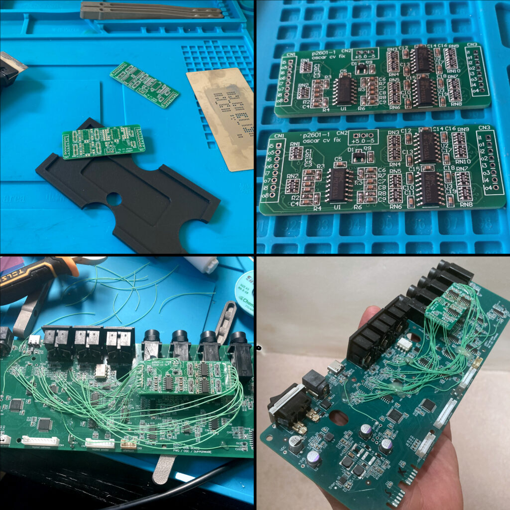
This is exactly the scale of bodge that I’d usually advise against: a two-hour mission of surgery that is barely worth doing over scrapping the board.
There is a miracle to this that I still cannot take for granted. I spent hours in the late 90s labouring over Veroboard prototypes, debugging track cuts and misplaced wire runs and solder shorts. As recently as 2010, a 2-layer plated-through PCB like this would have taken a minimum of three weeks to manufacture and cost about £400, and I’d have had to pay. These PCBs arrived from JLCPCB in Hong Kong five days after I placed the order, and cost me about £25 including shipping. The low cost and short turnaround of custom PCBs has completely changed our profession.
(All that said, I’m experimenting with the head tracker at the moment. Being a flex-rigid board makes these a special order even in Asia. It was a throwback to the Old Ways: ten bare PCBs did indeed take more than a month to arrive and cost over £500.)
Back to our story. A few postings ago, I remarked that I missed out some level-shifting circuitry to give the control voltages their proper range. Flippantly, I said:
Just don’t ask me to wire one into a rev. 1 prototype, unless you’re sponsoring me for charity.
— me, Little Green Wires
My attitude towards tempting fate is to do it as often and as brazenly as possible, to the extent that people begin to edge away. Wherever manufacturing is concerned, one should tease all possible misfortune out of the gods at the earliest opportunity, as it only gets more expensive later on. I really ought to know better because, of course, it turned out to be a lot worse than I’d thought. OSCar doesn’t produce a 0–5V range of control voltage, but about −3.5–+3.5V. I overlooked this for a few reasons, but two are most important.
First, I lent out my half-speed OSCar clone, which meant I didn’t have a reference circuit to hand. The clone stopped working properly at some point during ADC, and I couldn’t be bothered to fix it. The DAC still outputs control voltages on schedule, but something weird goes on when I try to play a note, like it’s resetting. Nobody alive is better positioned to debug it than me, but frankly I didn’t have a good enough reason to get it going again and I’m spread thinly enough.
Second, the DAC0808, that heroic high-speed 8-bit mono DAC that OSCar uses for everything, has a data sheet that is particularly short on description. It has none of the courtesies that manufacturers provide today: no reference design with commentary; no graphs of it in use; no ready-baked formulae to relate output to input. One must analyse the equivalent circuit or, more likely, wire-wrap one into a prototype. One would then, as we used to say, ‘adjust-on-design’ around it until it served its purpose, give tolerances a cursory thought, and bake whatever arbitrary values worked into the production schematic. Long story short: its output range is bipolar but you’d easily miss it, and the 80s were a different age.
Actually, the DAC works upside-down: it sinks more current from a reference as the number you feed it increases. This current is then converted into a voltage by a separate LF351 op amp that is essentially the output stage of the DAC and inverts the signal. Such things are easy to overlook in these days of large-scale integration. It’s been more than thirty years since you would see a new DAC without the output op-amp forming an inseparable part of the same chip. (That said, the DAC0808 is still in production, complete with entirely different pinouts for the surface-mount and through-hole chip versions: something else I’ve never seen on a production chip, and a landmine that I did side-step.)
I’m not using DAC0808 in the new design. Apart from the fact it needs a parallel input — a waste of 8 general-purpose pins these days — OSCar’s ‘it’s all one DAC’ trick is not one I’ll be repeating. As I covered in my previous post, it’s ingenious, but the exquisite timing and hackery required to dispatch all the voltages to their proper amplifiers is the principal reason for OSCar’s notoriously poor reliability. If we’re being fair, the final result is also a bit ‘steppy’: the filter and separation knobs feel very granular. The separation control is actually masked in OSCar’s maths so that only the five upper bits do anything, giving it a range of 0–31. One of my rules, succinctly put, is that workarounds with crap side-effects get fixed, and this is in that category.
The new OSCar instead gets a dual 8-bit DAC, one channel for each oscillator, which sweeps much of the old glue logic away. The control voltages, meanwhile, come out of 8 channels of 11-bit pulse-width modulation, which the microcontroller gives us for free.
(Why 11 bits? Many reasons. The original OTA chip which forms the voltage-controlled filters and amplifiers, the LM13600, is no longer in production. The LM13700, which is, is similar enough given our constraints that we can use it instead. Indeed, if you’ve got sharp eyes, you’ll see that Dave Spiers’s OSCar uses one as a replacement for one of his LM13600 chips, shown briefly in this video. Its internal circuitry, though, is slightly different, such that I anticipate needing to curve the control voltage to make it sound the same. The fact that those extra three bits might reduce the granularity of the controls is a bonus. 11 bits also gets us a nice carrier frequency: 72MHz/2^11 = 35kHz. Out-of-band for one, so you won’t ever hear it, but it’s also easy to design a control-rate filter that removes it well enough that we won’t hear modulation artifacts either.)
The PWM outputs are expanded to the correct range (on my second attempt) and smoothed down to the control rate so there’s effectively no ripple at audio frequency. Hence all the hand-wiring: every control voltage needs its own PWM-to-voltage converter. That is four bipolar signals for the VCF/VCA circuits (needing two op-amps). Four monopolar signals (needing only one op-amp) are abused as volume controls. Although, as we’ve covered before, only 7 of these control voltages really get used.
It doesn’t matter at all about the oscillator signals having the wrong voltage range, as there’s an AC capacitor between the audio output and the filter input on OSCar. As long as it wiggles at the right amplitude, which it does (with care), its absolute voltage is of no concern.
I’d give you a sound demo, and I’ve been promising these for weeks, but I’m miles away from my audio interface and you’ll get one soon enough.
The 0–3.3V restriction in the prototype control voltages prevented the filters from working in their most interesting range: the high-Q and the low-frequency regimes. The side-by-side comparison made this glaringly obvious. The OSCar whistles, growls, and makes Speak & Spell noises on demand and mine, er, didn’t. Filters being the most important part of OSCar, that obviously needed fixing for a trade show.
Nineteen pieces of hand-wiring later, and a lot of glue (as it’s destined for international travel) and we have our bodge. As this was a borderline decision, I chose not to remake the whole board for a couple of reasons: most importantly, I’d have to re-equip for production and that means trusting that every component I need will be in stock, and that neither I nor the stockists will make a mistake. Second, the fear in the back of my mind was that I’d bugger it up somehow and have nothing to show.
Hand-wiring, then, away from the comfortable, well-equipped lab at home (as I’m dog-sitting), is what I ended up doing.
Fortunately the planning paid off, because the bodge worked first time. There’ll be tweaks to the range for production, as there will be for every part of this synth, and I must very soon go and make the same mess of my own R&D prototype, but this will do for Superbooth. The real test will be whether it works the second time, when me and my soldering iron are replaced by journalists and their video cameras.
Leave a Reply